MMF remains the dominant fiber type used in local area networks (LANs) and data centers (DCs) because it almost always results in the lowest link cost (defined as the cost of the fiber, connectivity, and optical transceivers) for short distances. But gone are the days of OM1 and OM2 enjoying most of the deployments; higher-bandwidth fibers such as OM3 and OM4 now rule the day. And recently, OM5 joined the party. To understand the circumstances around why OM5 was born, it’s necessary to understand a few things about optical transceivers, and the standards which govern them.
First, we need to understand the distinction between standard- compliant transceivers, and proprietary transceivers. When we talk about standards-compliant transceivers in an Ethernet context, we’re talking about optical transmit and receive guidance which has been ratified as part of an IEEE 802.3 Ethernet standard. When we talk about proprietary transceivers, these are transceivers whose guidance is not part of the IEEE standard, either because the proposed physical media dependent (PMD) technology did not get enough member votes to be included in the standard, or because the transceiver utilizes a technology that was never offered up to become part of an open industry standard. It’s important to make this distinction between IEEE standards-compliant transceivers and proprietary transceivers, because the last few years have seen a proliferation of transceiver types available in the market, many of which are proprietary designs.
In the Ethernet realm from 1G up to 100G, all standards-compliant multimode transceivers have one thing in common: they utilize vertical-cavity surface-emitting lasers (VCSELs) which operate at the 850 nm wavelength. When VCSELs were first becoming commercially available, they were designed to produce light at 850 nm, which was one of the MMF specified operating wavelengths. Since the VCSELs were operating at 850 nm, subsequent enhancements in MMF fiber design and manufacturing were focused on optimizing the fiber bandwidth at 850 nm. For example, when OM4 fiber was introduced, it offered significant bandwidth improvements over OM3 at 850 nm, with OM4 offering 4700 MHz/km of effective modal bandwidth (EMB) at 850 nm, compared to the 2000 MHz/km provided by OM3.
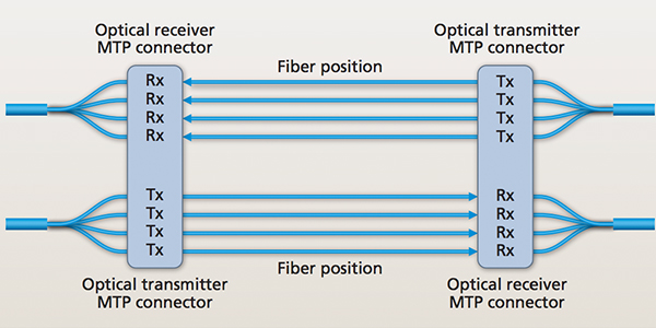
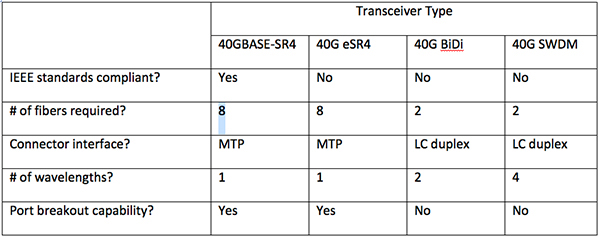
The second thing to know about multimode transceivers is the concept of parallel transmission, which some people refer to as parallel optics. For Ethernet speeds of 1G, 10G, and 25G, the multimode transceivers utilize two fibers, with one fiber carrying the transmit signal and one fiber carrying the receive signal. This is often known as serial transmission, and since these are 2-fiber devices, the connector interface into the transceiver is the LC duplex connector. However, with the adoption of the 40G 802.3ba Ethernet standard in 2010, the concept of parallel optics was introduced. In the case of the 40GBASE-SR4 transceiver, we have four fibers in parallel, each transmitting 10G per fiber, and another four fibers each receiving 10G per fiber. So these transceivers require eight fibers for a single channel, and as a result the multifiber MTP® connector is the defined connector interface into the transceiver. A major feature of parallel optics transceivers such as the 40GBASE-SR4 is that since individual fibers are each carrying a 10G signal, a single 40G MTP port on a switch can be broken out to four LC duplex 10GBASE-SR ports, which typically results in significant per-port power cost savings and higher switch port density. With this type of breakout, a line card with 32 x 40G ports can be broken out to 128 x 10G channels. For network managers who need port breakout functionality and need 40G distances beyond the 150 m which the 40GBASE-SR4 transceiver supports, a proprietary extended reach transceiver, the eSR4, has also been introduced.


