By David Hessong, Corning Incorprated
Cabling Advances for Data Center Interconnect
Cabling Advances for Data Center Interconnect
The data center interconnect (DCI) application was a hot topic at the recent Optical Fiber Communications conference in San Diego. Having emerged as an important and fast-growing segment in the network landscape, the space has been the focus of several exciting advances in fiber-optic cabling. This article will explore some of the reasons for the growth of this segment and focus on several of the new cabling technologies aimed at making this space more installer friendly.
Best Practices for Designing and Deploying Extreme-Density Data Center Interconnects
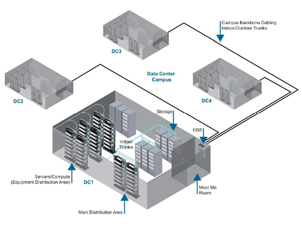
A quick internet search of large hyperscale or multi-tenant data center spending announcements returns several expansion plans, totaling into the billions of dollars. What does this kind of investment get you? Often, that answer is a data center campus consisting of several data halls in separate buildings that are often bigger than a football field and that typically have over 100 Tbps of data flowing between them (Figure 1).
 |
||
Figure 1. Sample data center campus layout |
Without diving too far into the details about why these data centers are growing so large, we can simplify the explanation to two trends. The first is the exponential east-west traffic growth machine-to-machine communication has created. The second trend is related to the adoption of flatter network architectures, such as spine-and-leaf or Clos networks. The goal is to have one large network fabric on the campus -- which drives the need for 100 Tbps of data or greater flowing between the buildings.
As you can imagine, building on this scale introduces several unique challenges across the network, from power and cooling down to the connectivity used to network the equipment together. On this last point, multiple approaches have been evaluated to deliver transmission rates at 100 Tbps (and eventually higher), but the prevalent model is to transmit at lower rates over many single-mode fibers. It is important to note that these lengths are often 2-3 km or shorter. Modeling shows that lower data rates over more fibers will remain the most cost-effective approach for at least the next few years. This cost modeling shows why the industry is investing so much money developing high-fiber-count cables and associated hardware.
Now that we understand the need for high-fiber-count cables, we can turn our attention to the alternatives on the market for data center interconnect. The industry has agreed that ribbon cables are the only feasible solution for this application space. Traditional loose tube cables and single-fiber splicing would take much too long to install and result in splice hardware too large to be practical. For example, a 3456-fiber cable using a loose tube design would require more than 200 hours to terminate assuming 4 minutes per splice. If you use a ribbon cable configuration, splicing time drops to less than 40 hours. In addition to these time savings, ribbon splice enclosures typically have four to five times the splice capacity in the same hardware footprint compared to single-fiber splice density.
Once the industry determined that ribbon cables were the best option, it was quick to realize that traditional ribbon cable designs were not able to achieve the required fiber density in existing conduit. The industry therefore set out to essentially double the fiber density in traditional ribbon cables.
Two design approaches emerged. The first approach uses standard matrix ribbon with more closely packable subunits, and the other approach uses standard cable designs with a central or slotted core design with loosely bonded net design ribbons that can fold on each other (see Figure 2).
 |
||
Figure 2. Different ribbon cable designs for extreme-density applications |
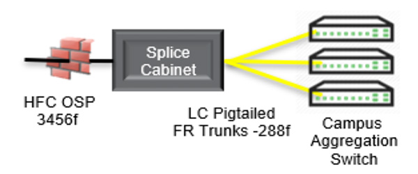
Now that we understand these new ribbon cable designs, we must also explore the challenges of terminating them. Since the cables carry an outside plant (OSP) flame rating they are required to transition to an inside plant (ISP) rated cable within 50 feet of entrance into the building per the National Electric Code (NEC). This is typically done by splicing pre-terminated MTP®/MPO or LC ribbon pigtails (cable with connectors preinstalled on one end) or stubbed hardware (hardware preloaded with pigtailed cable) in an extreme-density splice cabinet. This application is where end-users are no longer just evaluating the OSP cable design, but instead a full tip-to-tip solution for these costly and labor-intensive link deployments (Figure 3).
 |
||
| Figure 3. Transition splice cabinet from extreme-density OSP cable to pre-terminated ISP cable |
Several areas must be evaluated when deciding on the best tip-to-tip approach. Time studies have shown that the most time-consuming process is ribbon identification and furcation to prepare the ribbons to route into a splice tray. “Furcation” refers to the process of removing the cable jacket to protect the ribbons with tubing or mesh as they route inside the hardware to a splice tray. This step becomes more time consuming as the fiber count of the cable increases.
Often, hundreds of feet of mesh or tubing are required to install and splice a single 3456-fiber link. This same time-consuming process also must be completed for the ISP cables, whether they are pigtailed cables or in the form of stubbed hardware. Cables on the market today vary greatly in furcation time. Some incorporate routable fiber subunits on both the OSP and ISP cables (Figure 4), which require no furcation to bring the fibers to the splice tray, while others require multiple furcation kits to protect and route the ribbons (Figure 5). Cables with routable subunits are typically installed in purpose-built splice cabinets optimized with splice trays to match the fiber count of the routable subunit.
Another time-consuming task is ribbon identification and correct ordering to ensure the correct splicing. Ribbons need to be clearly labeled so they can be sorted after the cable jacket is removed, as a 3456-fiber cable contains 288 twelve-fiber ribbons. Standard matrix ribbons can be ink jet printed with identifying print statements, while many net designs rely on dashes of varying lengths and numbers to help identify ribbons. This step is critical because of the magnitude of fibers that must be identified and routed. This ribbon labeling also becomes critical in terms of network repair, when cables get damaged or cut after initial installation.
Forward-Looking Trends
Cable with 3456 fibers looks to be just a starting point, as cables with more than 5000 fibers have been discussed. Since conduit size is not getting bigger, the other emerging trend is to use fibers where the coating size has been reduced from the industry-standard 250 microns to 200 microns. Fiber core and cladding sizes remain unchanged, therefore not affecting optical performance. This reduction in fiber coating size can allow hundreds or thousands of additional fibers in the same size conduits as before.
The other trend will be the rising customer demand for tip-to-tip solutions. Sticking thousands of fibers in a cable solved the problem of conduit density but created many challenges in terms of risk and network deployment speed. Innovative solutions that help eliminate these risks and reduce deployment velocity will continue to mature and evolve.
Demands for extreme-density cabling seem to be accelerating. Machine leaning, 5G, and bigger data center campuses are all trending in a way that drive demand for these DCI links. These deployments will continue to challenge the industry to develop tip-to-tip solutions that can scale effectively to enable maximum duct utilization while not becoming increasingly cumbersome to deploy.

